28. Photodiodes, phototransistors, and transimpedance amplifiers
In lesson 21, we learned about photoresistors in which the resistance is dependent on the intensity of incident light. Photodiodes, on the other hand generate current upon being exposed to light (in contrast to an LED, which emits light when current flows through it).
Photodiodes come in many packages; the type we have in the lab is shown below.
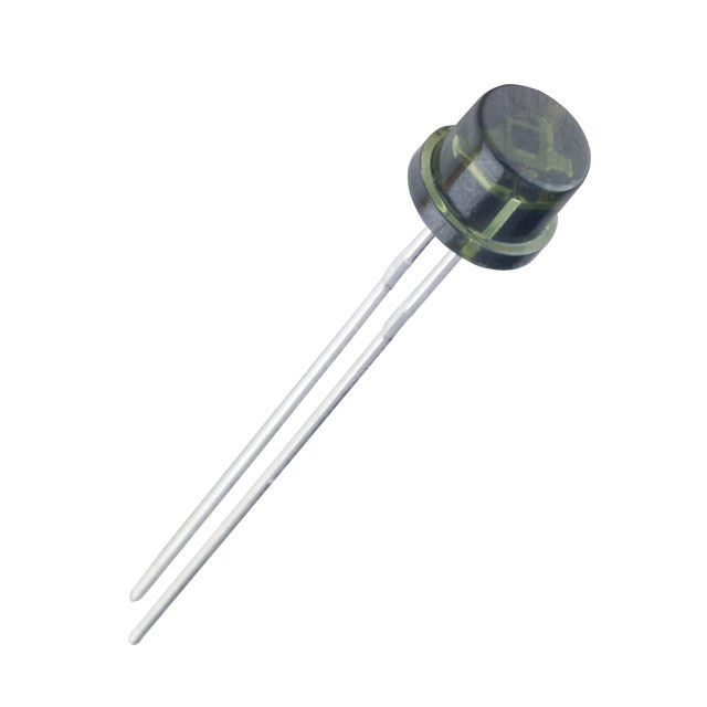
In this package, light impingent on the top leads to current flow.
Benefits of using photodiodes for optical detection
We already know how to sue photoresistors for detection of light, so why should we use photodiodes? Furthermore, as we will soon see, we need to convert the current generated by the photodiode, which adds complexity to circuits using them. Photodiodes do offer clear advantages.
Photodiodes have very fast response times, typically on the order of nanoseconds.
Photodiodes can be made to have spectral ranges from about 190 to 1100 nm, covering a wide range for measurement in biological systems. (An individual photodiode can be tuned to respond to a small band.)
Photodiodes have good linearity. That is, the function relating incident light intensity to current is linear over a large range of inputs.
Phototransistors
Photodiodes do suffer from the fact that they have very low output current, typically on the order of a microamp. As a remedy, we can employ phototransistors, a transistor in which the collect-base junction acts as a photodiode. Then, the gain \(\beta\) of the transistor amplifies the current, as described in the lesson on transistors. Since \(\beta\) is typically on the order of 100, phototransistors can produce currents on the order of 100 µA.
However, phototransistors have a nonlinear incident light-current relationship. Because of this nonlinearity, low-intensity light does not lead to significant current, so a photoresistor is less effective at detecting low light intensity levels, even though it has strong gain. Furthermore, phototransistors have much slower response times than photodiodes.
Transimpedance amplifiers
We can only measure potential differences, not currents, so we need to convert the current flowing through a photodiode or phototransistor into a voltage. The simplest way to make this conversion is simply to put a resistor between the photodiode and ground and measure the voltage, knowing that \(V = I R\). This is problematic because the resistor, by design, provides impedance to the input current. If the current source has poor compliance (meaning that the current is strongly effected by the output voltage), then the voltage across the resistor will affect the current, and an accurate current measurement is not possible. So, we need a conversion of current to voltage that has small impedence in the output. This is accomplished using an op-amp configured as a transimpedance amplifier, shown below.

Here, the current source could be a photodiode, phototransistor, or any other current course. In what follows, we will use photodiode, with its symbol looking like that of an LED, except with light arrows coming in.

Again recalling the rules of op-amps, the voltage at both inputs is the same, and since the noninverting input is connected to ground, both input voltages are zero relative to ground. Furthermore, the current flowing through the op-amp is close to zero so that the current flows through the resistor. The potential across the resistor is \(V_\mathrm{ground} - V_\mathrm{out} = -V_\mathrm{out}\). So, the output voltage is proportional to the current, \(V_\mathrm{out} = -I R\). The name “transimpedance amplifier” comes from this fact; the “gain” of the amplifier has units of resistance (impedance). These are also sometimes called transresistance amplifiers or current-to-voltage converters.
Dealing with capacitance in the photodiode
The above transimpedance amplifier can give rise to oscillations. This is because the photodiode has some small, but nonzero, capacitance. Combined with the resistor, this gives a low pass filter. The filter gives a 90° phase shift at high frequencies. The op-amp also has a lagging phase shift, which, when added to that of the low-pass filter, gives a total phase shift of 180°. The result is positive feedback, which can give rise to oscillations. To remedy this, a we add a small capacitor in parallel with the resistor, as shown below. This serves to damp out the oscillations.

Another option is to introduce a reverse bias, where a positive voltage is set up across the photodiode, as shown below. This results in an additive offset to the current through the photodiode. The advantage is that the capacitance of the photodiode is reduced (for physical reasons related to how diodes function) and results in a faster response time. The disadvantage is that this usually results in more noise and makes measuring low-intensity light more difficult. Oscillations are possible, so it is advisable to consider adding a capacitor across the resistor.
